M-HC-010
Key features:
Pressure on demand
Solenoid activated
High pressure – up to 700 bar (10,000 psi)
Max. inlet pressure = 207 bar (3,000 psi)
Fast fill – system flows up to 100 l/min
Extended service life
Robust design
Flexible design; several boosters/intensification factors
Description
The M-HC-010 In-line Intensifier System is designed to boost the hydraulic pressure from the pump to the workload. The system operates by solenoid activation. The operator is in full control of the system and can decide if a boosted pressure to the workload should be applied.
The system is dynamical by means of being able to provide flow at high pressure for intermittent use (< 10 min duty cycle).
Typical applications
Mobile attachments; motors – steering systems – cutters – crushers – shears, off highway equipment, injection molding machines and hydraulic presses. Applicable to machines with insufficient pump capacity to prevent machine stoppage when peak pressures occur.
Easy installation
M-HC-010 is provided with four mounting holes for through bolt installation. The four connection ports are placed logically in pairs and in line of each other on the HIC block. All surfaces are electroplated for good protection and fine surface finish.
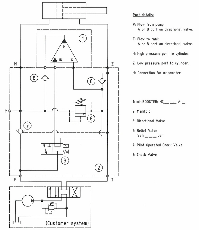
Functions
The system operates by solenoid activation. The operator is in full control of the system and can decide if a boosted pressure to the workload should be applied.
A relief valve is installed to control the maximum allowable pressure that the system can output, and allowing the booster to go for a higher end pressure producing flow at the decided pressure.
Function diagram
010-01
Connection types
| Connection | P / T / Z / H | M (P / H / 1), F1 / F2 |
|---|---|---|
| M-HC2D-01_-1L100 | 1/2" BSPP | 1/4" BSPP |
| M-HC3-01_-1L100 | 1/2" BSPP | 1/4" BSPP |
| M-HC6D-01_-1L55 | 1/2" BSPP | 1/4" BSPP |
| M-HC6D-01_-1L100 | 1/2" BSPP | 1/4" BSPP |
| M-HC6D-01_-1L200 | 1 1/4" BSPP | 1/4" BSPP |
| M-HC6D-01_-1L400 | 1 1/4" BSPP | 1/4" BSPP |
Flange mounting
Flange mounting drawing HV-399-02
Fluids and materials
Additional information is available on the website under Products → General specifications.
Ordering an M-HC-010
Ordering example of an M-HC-010 for 700 bar, connection flange with HC3 i = 3.2, static use:
M-HC3-010-FL55 mounted with HC3-3.2-A-D
Guidance to calculate the intensification factor for dynamic or static use is at the bottom of this section.
Attention note!
Valve pre-settings are required, please specify when ordering the intensifier system.
Selection of intensifier system
| Ordering code | Connection | Bypass flow | Max. pressure | Weight | Dimension drawing PDF |
|---|---|---|---|---|---|
| M-HC2D-010-FL55 | Flange | 55 l/min | 700 bar | 9.0 kg | M-HC2D-010-FL |
| M-HC3-010-FL55 | Flange | 55 l/min | 700 bar | 7.5 kg | M-HC3-010-FL |
| M-HC6D-010-1L55 | Tube | 55 l/min | 700 bar | 32.0 kg | M-HC6D-010-1L |
| M-HC2D-010-FL100-PVG32 | Flange | 100 l/min | 700 bar | 9.0 kg | M-HC2D-010-FL100-PVG32 |
| M-HC3-010-FL100-PVG32 | Flange | 100 l/min | 700 bar | 7.5 kg | M-HC3-010-FL100-PVG32 |
| M-HC6D-010-1K | Tube | 100 l/min | 500 bar | 31.5 kg | M-HC6D-010-1K |
The intensification factor depends on available inlet and desired outlet pressure. To calculate the initial factor, use the following formular:
i = Desired high pressure / pump pressure
Desired pressure: 550 bar
Pump pressure: 207 bar
i = 550 / 207 = 2.7
For static use: Select an intensification factor higher or equal to the calculated value. In this example calculated i = 2.7, select factor i = 2.8 for an HC3 booster.
For dynamic use: Select an intensification factor 40% higher than the calculated value. In this example calculated i = 550 / 207 = 2.66 + 40% = 3.7, select factor i = 4.0 for an HC3 booster. The desired pressure of 550 bar is finally adjusted with the Relief Valve (6).
Max. tightening torque BSPP
| P / T | H / Z | |
|---|---|---|
| 1/2" BSPP | 1/2" BSPP | |
| with steel washer | 13.0 da/Nm | 13.0 da/Nm |
| with cutting edge | 13.0 da/Nm | 13.0 da/Nm |
miniBOOSTER Hydraulics A/S
Fynsgade 3
DK - 6400 Sønderborg
Tel: +4574429292
Fax: +4574424204
info@minibooster.com
Monday-Friday: 8AM -5PM
(GMT +1)